Fragen und Antworten zur FS2 Questions and answers regarding FS2
1. Wie gross sollte die Getriebeuntersetzung zwischen Motor und Montierungsachse
sein? (2) Der Antrieb muß ausreichend Drehmoment liefern um das Teleskop auch unter den ungünstigsten Bedingungen noch zuverlässig bewegen zu können. Ungünstig bedeutet: Tiefe Temperatur (zähes Fett in den Lagern) und schlecht ausbalanciertes Teleskop (wenn z.B. irgendwelches Zubehör montiert ist). (3) Es ist wünschenswert, daß das Teleskop möglichst schnell schwenken kann. Das Problem ist nun, daß die Anforderungen (1) und (2) eine möglichst große Untersetzung verlangen, während (3) eine möglichst kleine Untersetzung erfordert. Es gilt also einen guten Kompromiss zu finden. Zunächst
sollte man sich klar machen, daß die drei Anforderungen unterschiedlich
wichtig sind: (1) und (2) sind unverzichtbare Forderungen, während
(3) "nur" ein Wunsch ist. Mit einer Montierung, die zwar langsam schwenkt,
aber vibrationsfrei und zuverlässig läuft können Sie arbeiten.
Die
Forderung (1) erfordert eine Untersetzung von mindestens 1500:1 wenn ein
Schrittmotor verwendet wird, der gut für Mikroschrittbetrieb geeignet
ist (z.B. SECM4, SECM8, ESCAP P530 oder ESCAP PH632).
Den Unterschied zwischen Mikroschritt und Halbschritt finden Sie hier erklärt. Um
die Forderung (2) zu erfüllen müssen Sie erst einmal wissen,
wie groß das benötigte Drehmoment an der Schneckenwelle ist.
Dieses Drehmoment hängt von sehr vielen Einflüssen ab:
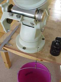
Montieren
Sie eine runde Scheibe am Ende der Schneckenwelle und wickeln Sie eine
Schnur auf diese Scheibe (siehe Bild rechts). Das eine Ende der Schnur
wird an der Scheibe befestigt. Das andere Ende lassen Sie senkrecht herunter
hängen und befestigen einen Eimer mit Gewichten daran. Nun vergrößern
Sie dieses Gewicht solange, bis die Schneckenwelle in jeder Winkelstellung
von selbst anfängt sich zu drehen. Machen Sie diesen Versuch unter
den ungünstigsten zu erwartenden Bedingungen, d.h. möglichst
tiefe Temperatur und schlecht ausbalanciertes Teleskop.
|
1.
What gear ratio should I use between the motor and the axis of the mount?
If you want to dimension the gear ratio for your mount there are three important demands: (1)
The telescope must move without any visible vibrations. This means that
the vibrations caused by the motor must be significantly smaller than the
resolution of the optics.
The problem is that the demands (1) and (2) require a large gear ratio while demand (3) requires a ratio as small as possible. A good compromise must be found. At
first please make yourself clear that the demands (1) and (2) are essential
requirements while (3) is "only" a wish. With a mount which slews slowly
but runs reliable and free of vibrations you can work.
Demand
(1) requires a gear ratio of at least 1500:1 if a good stepper motor suitable
for microstep mode is used (for example SECM4, SECM8, ESCAP P530 or ESCAP
PH632).
To
fulfill the demand (2) you must at first know the required torque at the
worm shaft of your mount. This torque depends on lots of points:
|
4.
Wie klein sind die Mikroschritte bei der FS2?
Bei
der FS2 entspricht ein Vollschritt 64 Mikroschritten.
Einige
Schrittmotor-Hersteller geben die absolute Winkelgenauigkeit im Datenblatt
an:
Generell
kann man davon ausgehen, daß sich die Welle eines Schrittmotors
um etwa einen Vollschritt verdreht wenn man das Lastmoment von Null auf
den zulässigen Maximalwert erhöht. Ein Vollschritt entspricht
bei der FS2 64 Mikroschritten.
Einige nützliche Formeln: Grösse
eines Mikroschritts in Bogensekunden (am Fernrohr):
Grösse
eines Halbschritts in Bogensekunden (am Fernrohr):
Grösse
eines Vollschritts in Bogensekunden (am Fernrohr):
Grösse
eines Mikroschritts in Zeit-Sekunden (am Fernrohr):
Grösse
eines Halbschritts in Zeit-Sekunden (am Fernrohr):
Grösse
eines Vollschritts in Zeit-Sekunden (am Fernrohr):
"M1_VS/U"
ist die Anzahl der Vollschritte pro Motorumdrehung
|
4.
How small are the FS2 microsteps?
With
the FS2 one full step equals 64 microsteps.
1. It must be guaranteed that the motor delivers still enough torque. (See the question about gear dimensioning above) 2.
It is not guaranteed that all microsteps are equal in size. It depends
on the motor type how big the differences are. Motors which were special
designed for microstep mode make more regular microsteps than other motors.
You'll find some examples here.
Some useful formulas: Size
of a microstep at the telescope in arc seconds:
Size
of a halfstep at the telescope in arc seconds:
Size
of a Fullstep at the telescope in arc seconds:
Size
of a microstep at the telescope in time seconds:
Size
of a halfstep at the telescope in time seconds:
Size
of a Fullstep at the telescope in time seconds:
"M1_FS/R"
is the number of full steps per motor revolution
|
7.
Wie wähle ich einen geeigneten Winkel-Encoder aus?
Beachten Sie bitte, daß die Encoder nicht beliebig schnell verdreht werden dürfen, denn sonst wird der Winkel falsch gemessen. Die Encoder werden mit 8 kHz abgetastet, so dass die maximale Drehgeschwindigkeit 2000 Linien pro Sekunde beträgt. Diese Geschwindigkeit darf auch nicht kurzzeitig überschritten werden. Zwei
Beispiele:
Die
Winkelauflösung eines Encoders wird so berechnet:
Zwei
Beispiele:
Sie sehen, daß der Vorteil einer hohen Winkelauflösung mit dem Nachteil einer kleineren zulässigen Drehgeschwindigkeit erkauft wird. Wenn
Sie den Encoder direkt auf der Montierungsachse montieren können,
dann wäre ein Encoder mit 2000 Linien die richtige Wahl. Leider geht
das aber meistens nicht, weil in der Rektaszensionsachse ein Polsucher
steckt oder weil an der Deklinationsachse ein Gegengewicht befestigt ist.
Andere
Möglichkeiten der Ankopplung des Encoders sind:
|
7.
How do I choose a suitable angle encoder?
Please note that the encoders may not be rotated at any speed desired, because the the angle would be measured wrongly. The encoders are polled with 8 kHz, so that the maximum rotation speed is 2000 lines per second. This speed may not even be exceeded for a short time. Two
examples:
The
angle resolution of an encoder is calculated as follows:
Two
examples:
As you can see, the advantage of a high resolution is connected to the disadvantage of a smaller permissible maximum rotation speed. If
you mount the encoder direct onto the axis of the mount, then an encoder
with 2000 lines is the best choice. Unfoutunately this is not possible
in most cases, because there is a polar alignment scope in the RA axis
or a counterweight at the Dec axis.
Other
coupling methods for the encoder:
|
8.
Was ist die Autoguider-Schnittstelle?
Diese
Schnittstelle besteht aus zwei Steckverbindern, die in die FS2 eingebaut
werden: Eine 15-polige Buchse für die ST-4 und ST-6, und eine 6-polige
Buchse für die ST-7, ST-8 und alle Meade Kameras.
Siehe auch: Wie schliesse ich einen Autoguider an die FS2 an? |
8.
What is the autoguider interface?
This interface consists of two connectors that are built into the FS2. One is a 15-pin connector for ST-4 and ST-6, the other is a 6-pin connector for ST-7, ST-8 and all Meade cameras. The autoguider (for example ST-4) tracks a guide star, and if it detects that the star is not where it should be, then a relay switches for a short time. There are 4 relays in the ST-4, one for each direction. The outputs (contacts) of the relays are connected to the FS2 autoguider input. When a signal comes through this interface then the FS2 will turn one of the motors at a low speed, moving the star back to the place where it should be. See also: How to connect an autoguider to the FS2 |
11.
Welche Positionier-Genauigkeit kann man mit der FS2 erwarten?
Die
Positionier-Genauigkeit hängt im Wesentlichen davon ab, wie genau
die Pol-Justierung durchgeführt wurde.
In
der Praxis ist aber die Pol-Justierung nie perfekt. In diesem Fall gilt:
Der Positionier-Fehler wird nicht größer werden als der Winkel
zwischen der Rektaszensions-Achse und dem Himmelspol.
Außerdem
wird der Positionier-Fehler größer, wenn die Montierung Fehler
aufweist:
Anleitung
zur genauen Polachsen-Justierung nach der Scheiner-Methode
|
11.
Approximately what kind of pointing accuracy can I expect with the FS2?
This
depends on the accuracy of the polar alignment.
But in practice the polar alignment will never be perfect. In this case the pointing error will never become bigger than the angle between the RA axis and the celestial pole. A smaller slewing distance means a smaller pointing error. Additionally
the pointing accuracy will be affected by errors in the mount:
How to make the exact polar alignment (Scheiner method) click here |
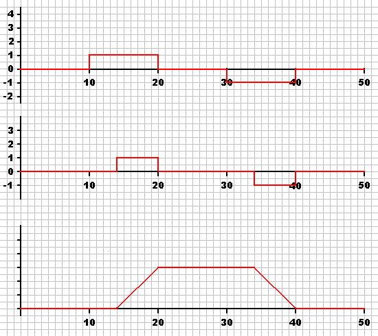
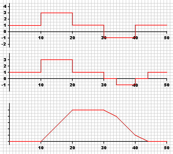
Beispiel
1: Deklinations-Achse,
ohne Getriebespiel-Ausgleich Die
obere Kurve zeigt die Geschwindigkeit des Dekl.-Motors. Von t=10 bis t=20
wird die N Taste gedrückt, und von t=30 bis t=40 wird die S Taste
gedrückt.
Example
1:
The
upper graph shows the speed of the DE motor. From t=10 to t=20 the N button
is pressed, and from t=30 to t=40 the S button is pressed.
|
|
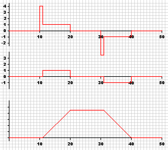
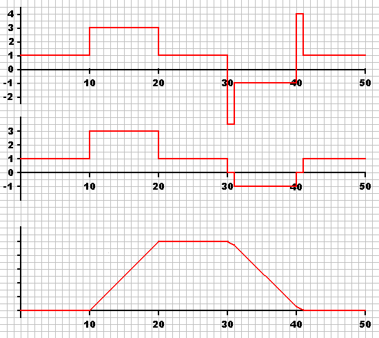
Beispiel
2: Deklinations-Achse,
mit Getriebespiel-Ausgleich Die
obere Kurve zeigt die Geschwindigkeit des Dekl.-Motors. Von t=10 bis t=20
wird die N Taste gedrückt, und von t=30 bis t=40 wird die S Taste
gedrückt. Wenn sich die Drehrichtung geändert hat, dann läuft
der Motor für eine kurze Zeit schneller, um das Getriebe-Spiel möglichst
schnell auszugleichen.
Example
2: DE axis,
The
upper graph shows the speed of the DE motor. From t=10 to t=20 the N button
is pressed, and from t=30 to t=40 the S button is pressed. When the turning
direction has changed, the motor runs faster for a short time.
|
|
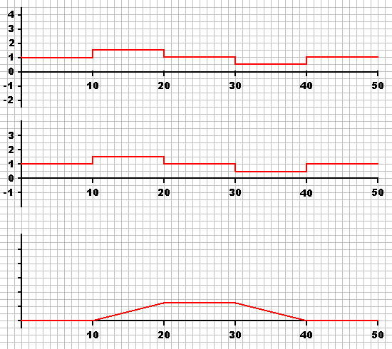
Beispiel
3: Rektaszensions Achse, Korrektur-Geschwindigkeit kleiner als 1x
Die
obere Kurve zeigt die Geschwindigkeit des Rekt.-Motors. Von t=10 bis t=20
wird die W Taste gedrückt, so dass der Motor schneller läuft.
In diesem Beispiel ist die Korrektur-Geschwindigkeit 0.5x. Von t=30 bis
t=40 wird die O Taste gedrückt, so dass der Motor langsamer läuft.
Example
3: RA axis,
The
upper graph shows the speed of the RA motor. From t=10 to t=20 the W button
is pressed, so that the motor runs faster. In this example, the correction
speed is 0.5x the sidereal speed. From t=30 to t=40 the E button is pressed
and the motor runs slower.
|
|
Beispiel
4: Rektaszensions Achse, Korrektur-Geschwindigkeit grösser als 1x,
kein Getriebespiel-Ausgleich Die
obere Kurve zeigt die Geschwindigkeit des Rekt.-Motors. Von t=10 bis t=20
wird die W Taste gedrückt, so dass der Motor schneller läuft.
In diesem Beispiel ist die Korrektur-Geschwindigkeit 2x. Von t=30 bis t=40
wird die O Taste gedrückt, so dass der Motor langsamer läuft.
Example
4:
The
upper graph shows the speed of the RA motor. From t=10 to t=20 the W button
is pressed, so that the motor runs faster. In this example, the correction
speed is 2x the sidereal speed. From t=30 to t=40 the E button is pressed.
In this case the turning direction changes.
|
|
Beispiel
5: Rektaszensions Achse, Korrektur-Geschwindigkeit grösser als 1x,
mit Getriebespiel-Ausgleich Wie
Beispiel 4, aber jetzt mit Getriebespiel-Ausgleich.
Example
5:
This
is the same as example 4, but now with clearance compensation. From t=10
to t=20 the W button is pressed. There is no clearance compensation necessary
because the turning direction does not change.
|
13.
Kann die Nachführ-Geschwindigkeit auf "King Rate" eingestellt werden?
Ja
und nein.
Da
bei der Kometen-Nachführung die Geschwindigkeit in beiden Achsen frei
programmierbar ist, können sie hier natürlich auch die "King-Rate"
einstellen. Als Mittelwert können Sie +0.41 beim Parameter "Komet_RA"
eintragen.
Wenn
Ihre Nachführung geringfügig zu schnell oder zu langsam läuft
dann können Sie die Kometen-Nachführung verwenden um dieses Problem
zu korrigieren.
Umrechnung von anderen Einheiten in "Minuten pro Tag":
Wenn
die Nachführung zu schnell läuft, muss der "Komet-RA" Wert vergrössert
werden (positives Vorzeichen).
Und hier sind die Umrechnungsfaktoren für die Kometen-Nachführung mit der Deklinations-Achse: Umrechnung von anderen Einheiten in "Bogenminuten pro Tag":
|
13.
Does the FS2 support "King Rate" tracking?
Yes
and no.
In comet mode the tracking speed is programmable for both axes, and of course you can enter the King rate too. As a gereral purpose mean value for all latitudes enter +0.41 as the "comet_RA" parameter. The
exact values, which depend on latitude, declination and hour angle, can
be found here.
If
your mount tracks a little bit too fast or too slow, you can use the comet
tracking function to correct this problem. First you must know the size
of the error, given in the unit "minutes per day".
Conversion from other units into "minutes per day":
If
the tracking speed is too fast, the "Comet_RA" value must be increased
(positive sign).
And here are the conversion factors for comet tracking with the declination axis: Conversion from other units into "minutes of arc per day":
|
15.
Umrechnung von Winkeleinheiten
h
Stunden
24h
= 86400s = 360° = 21600' = 1296000"
|
15.
Angle units conversion
h
Hours
24h
= 86400s = 360° = 21600' = 1296000"
|
16.
Kann man die FS2 bei solchen Montierungen verwenden, die an der Deklinationsachse
einen Tangential-Arm Antrieb haben?
Ja,
das ist möglich. Aber natürlich ist der Schwenkbereich eingeschränkt,
weil die Länge der Gewindespindel begrenzt ist.
Die effektive Getriebeuntersetzung wird so berechnet: Getr = 2 x 3.1415 x V x R / S mit
V = Untersetzungsverhältnis zwischen Motor und Gewindespindel
Das erforderliche Drehmoment wird (unter Vernachlässigung der Reibung) so berechnet: M = F x S / (2 x 3.1415) mit
F = axiale Kraft an der Mutter in N (Newton)
|
16.
Can the FS2 be used with mounts which have a tangent drive at the declination
axis?
Yes,
that's possible. But of course the slewing range is limited because of
the length of the threaded rod.
The effective gear ratio can be calculated with this formula: Gear = 2 x 3.1415 x V x R / S with
V = Gear ratio between the motor and the threaded rod
The required torque can be calculated with this formula (ignoring the friction): M = F x S / (2 x 3.1415) with
F = axial force at the nut in N (Newton)
|
17.
Wie kann ich feststellen, welche der drei FS2 Versionen (12V, 30V oder
40V) ich bekommen habe?
Die 12V Version (Betriebsspannung zwischen 9V und 15V) hat entweder einen gelben Aufkleber "Betriebspannung: 9-15V" oder keinen Aufkleber. Die 30V Version (Betriebsspannung zwischen 9V und 30V) hat einen gelben Aufkleber "Betriebspannung: 9-30V". Die 40V Version (Betriebsspannung zwischen 10V und 15V, eingebauter Spannungswandler auf 40V) hat einen roten Aufkleber "Betriebspannung: 10-15V". |
17.
How can I see which of the three FS2 versions (12V, 30V or 40V) I have
got?
The 12V version (Supply voltage between 9V and 15V DC) has either a yellow sticker "Supply Voltage: 9-15V DC" or no sticker at all. The 30V version (Supply voltage between 9V and 30V DC) has a yellow sticker "Supply Voltage: 9-30V DC". The 40V version (Supply voltage between 10V and 15V DC, built-in 40 Volts converter) has a red sticker "Supply Voltage: 10-15V DC". |
18.
Umrechnung von Einheiten Units conversion
Länge Length
Drehmoment Torque
Kraft Force
Gewicht Weight
|
19.
Wie ermittelt man bei einer Montierung eine unbekannte Getriebeuntersetzung?
Es gibt mehrere Möglichkeiten: 1. Für einige Montierungen finden Sie die Daten auf der letzten Seite in der FS2 Anleitung. 2. Oder fragen Sie bei ASTRO ELECTRONIC nach. 3.
Die gesamte Untersetzung setzt sich normalerweise aus zwei Teilen zusammen:
Bei der FS2 müssen Sie das gesamte Untersetzungsverhältnis einstellen, also vom Motor bis zur Montierungsachse. Mit anderen Worten: Wieviele Umdrehungen macht die Motorwelle, bis sich das Teleskop um 360° gedreht hat? Das gesamte Untersetzungsverhältnis entspricht dem Produkt von (a) und (b). Wenn Sie bei der FS2 das Untersetzungsverhältnis zu groß einstellen, dann wird der Motor zu schnell laufen. Und wenn der eingestellte Wert zu klein ist, dann läuft der Motor zu langsam. Stellen
Sie zunächst irgendein Untersetzungsverhältnis ein, und versuchen
Sie dann einen Stern mit einem Fadenkreuzokular zu verfolgen.
Sie
können die Nachführ-Geschwindigkeit auch ohne Sterne überprüfen.
Getr
= G x T / 86163 sec
Sie
können den Versuch natürlich auch über eine kürzere
Zeitdauer machen. Wenn Sie die Montierung nur über 90 Grad laufen
lassen, dann dauert der Versuch nur 86163 sec / 4 = 21541 sec.
Getr
= G x T / 215.4 sec
|
19.
How to find out an unknown gear ratio of a mount
There are several methods: 1. For some popular mounts you will find the data on the last page in the FS2 instruction manual. 2. Or ask ASTRO ELECTRONIC. 3.
Normally the total gear ratio consists of two parts:
The
FS2 must know the total gear ratio from the motor to the telescope axis.
With other words: How many revolutions does the motor make while the telescope
makes one 360° revolution?
If you set the gear parameter too big, then the motor will run too fast. And if the parameter is set too small, then the motor will run too slow. At
first you should set the gear parameter to a value which you think is approximately
correct. Then try to track a star in a reticle eyepiece.
It
is also possible to check the tracking speed without stars.
Gear
= G x T / 86163 sec
Of
course it is also possible to make this test in a shorter time.
Getr
= G x T / 215.4 sec
|
20.
Wie beantworte ich die Ost / West Frage bei der Eingabe des Referenzobjektes?
Bei
einer deutschen Montierung gibt es grundsätzlich immer zwei Möglichkeiten,
wie man das Teleskop auf einen Punkt am Himmel ausrichten kann. Wenn beispielsweise
das Teleskop auf einen Stern im Süden zeigt, dann kann sich das Teleskop
entweder links oder rechts der Montierung befinden. (Für Beobachter
auf der südlichen Halbkugel: Wenn das Teleskop auf einen Stern im
Norden zeigt ... )
Methode 1, eindeutig und uneingeschränkt gültig: 1.
Wenn das Fernrohr in Richtung Osten zeigt (beispielsweise im Herbst abends
in Richtung Andromeda) dann ist die Antwort "O".
Methode 2, eindeutig und uneingeschränkt gültig: Wenn
die Montierung einen Deklinations-Teilkreis hat, dann schauen Sie sich
diesen Teilkreis mal genau an. Die Skala geht von -90° über 0°
nach +90°, und dann auf der anderen Seite über 0° wieder zurück
nach -90°. Das bedeutet dass jeder Wert zweimal vorkommt (ausgenommen
die Endwerte -90° und +90°). Daher gibt es eine Mehrdeutigkeit,
denn die FS2 kann ja nicht wissen in welcher Hälfte die Markierung
steht.
Methode 3, leicht zu merken, aber nicht immer ganz eindeutig: Grundannahme: Das Teleskop befindet sich bei der deutschen Montierung immer höher als das Gegengewicht. Wenn sich das Teleskop auf der westlichen Seite befindet, dann können Sie die östliche Himmelshälfte beobachten, also beantworten Sie die Frage mit "Ost". Allerdings ist es möglich, das Teleskop etwas über den Meridian hinaus in die westliche Himmelshälfte zu schwenken. Auch in diesem Fall muss die Frage mit "Ost" beantwortet werden. Wenn
sich das Teleskop auf der östlichen Seite befindet, dann können
Sie die westlicher Himmelshälfte beobachten, also beantworten Sie
die Frage mit "West". Allerdings ist es möglich, das Teleskop etwas
über den Meridian hinaus in die östliche Himmelshälfte zu
schwenken. Auch in diesem Fall muss die Frage mit "West" beantwortet werden.
|
20.
How do I answer the East / West question when entering the reference object?
With
a German equatorial mount there are always two possibilities how to point
the scope to a point in the sky. For example if the scope points to a star
in the south, the scope can be either on the west side of the mount or
on the east side. (For observers in the southern hemisphere: If the scope
points to a star in the north ...)
Method 1, clear and always valid: 1.
If the telescope points to the eastern sky (for example to Andromada in
Autumn evenings), the correct answer is "East".
Method 2, clear and always valid: If
your mount has a setting circle at the declination axis, then have a closer
look at this circle. The scale goes from -90° over 0° to +90°,
and then on the other side over 0° back to -90°. That means every
value exists twice (except the end values -90° and +90°). So we
have a multivaluedness, because the FS2 can't know in which half of the
circle the pointer is.
Method 3, very easy, but not always clear: Assumption: The counterweight of the german equatorial mount is always lower than the telescope. If your telescope is to the west of the mount, you can look to objects from about the local meridian to the eastern part of the sky, so input East. However, depending on the mount and the telescope you can for example move your scope past (west of) the local meridian - even then you would input east! If
your telescope is on the east side of the mount, it can only look from
about the meridian to the western part of the sky, so choose West. However,
depending on the mount and the telescope you can for example move your
scope past (east of) the local meridian - even then you would input west!
|
21.
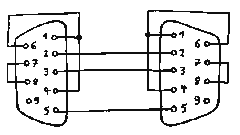
Wie muss das serielle Kabel vom PC zur FS2 verdrahtet werden?
Es gibt mehrere Möglichkeiten: 1. Nehmen Sie ein Kabel, welches an beiden Enden jeweils eine Buchse hat. Alle 9 Leitungen müssen 1:1 verbunden sein. Solche Kabel können Sie in verschieden Längen bei ASTRO ELECTRONIC kaufen. 2.
Löten Sie sich das Kabel selber zusammen: Es genügt ein 3-adriges
Kabel. Verbinden Sie Pin 2 mit Pin 2, Pin 3 mit Pin 3 und Pin 5 mit Pin
5.
Hinweis
zur Zeichnung: Um Verwechslungen zwischen Löt- und Steck-Seite zu
vermeiden, sind bei den D-Sub Steckern IMMER die Pin-Nummern entscheidend,
und nicht die grafische Darstellung.
|
21.
How to make a serial cable from the PC to the FS2
There are several possibilities: 1. Take a cable with a female DB9 connector at both ends. All 9 pins must be wired 1:1. You can order such cables in various lengths from ASTRO ELECTRONIC. 2.
Make a cable yourself. A 3-wire cable is sufficient. Connect pin 2 with
pin 2, pin 3 with pin 3 and pin 5 with pin 5.
I
order to avoid prpblems when you look at the connector from the wrong side,
please note that the pin numbers are important, and not the graphical representation
of the connector.
|
22.
Wie gut ist die Nachführ-Genauigkeit der FS2?
Die Genauigkeit der Nachführ-Geschwindigkeit ist hauptsächlich durch drei Einflüsse begrenzt: 1. Der durch atmosphärische Refraktion entstehende Fehler, weitere Informationen siehe unter King Rate. Diesen Fehler kann die FS2 mit der variablen Kometen-Nachführung ausgleichen. 2.
Die Genauigkeit des internen Quarzes, die Abweichung ist maximal +-100ppm,
das entspricht +-0.01%. Dieser Fehler kann ausgeglichen werden, indem die
Kometen-Nachführung verwendet wird. Der unter "Komet_RA" einzustellende
Wert wird so berechnet:
3. Der Fehler der durch ungenaue Polausrichtung entsteht. Eine ausführliche Anleitung zur genauen Polausrichtung nach der "Scheiner-Methode" finden Sie hier. |
22.
What tracking accuracy can I expect with the FS2?
The tracking accuracy is limited mainly be three points: 1. The error caused by atmospheric refraction. Please have a look at King Rate for more informations about this. 2.
The accuracy of the internal crystal oscillator, +-100ppm or 0.01%.
3.
The error caused by incorrect polar alignment of the mount. You find a
detailed description of the "Scheiner Method" for polar alignment here.
Sorry, in german language only.
|
23.
Wie stelle ich das Datum und die Uhrzeit ein?
Normalerweise
ist es gar nicht notwendig das Datum und die Uhrzeit einzustellen. Sie
können die GoTo-Funktion verwenden ohne zuvor das Datum und die Uhrzeit
eingegeben zu haben.
Beispiel:
|
23.
How to enter the date and time?
Normally
it's not necessary to enter the date and time into the FS2.
|
24.
The basic principle how to set up the system for the first time is as follows (valid for a german equatorial mount, for both hemispheres): 1. The mount must be roughly polar aligned. 2.
Set all parameters according to the mount type (especially the gear ratio,
and full steps per motor revolution). This makes sure that the motors run
at the correct speed, but not necessarily in the correct direction.
3. Switch on the FS2 and check the turning direction of the RA motor. Stars must stand still in the eyepiece. If the direction is wrong, reverse the setting of the "M1_L/R" parameter. Check again if the stars stand still. If they don't, then either "M1_gear" or "M1_FS/R" or "M1_L/R" are set incorrectly. 4.
Point the scope to a known bright star in the east. Use the "ref.obj" function,
choose the star from the list and answer the E/W question with "E" (left
button). Now press the "N" (upper) button and check if the scope slews
towards north (towards positive declination). Do not look at the display
(it will show increasing declination in any case), the question is if the
scope really slews towards north. You can select a higher slewing speed
by pressing shift-N several times, so that you can see the movement better.
5. If encoders are used, then the encoder's turning directions must be checked as described in the manual. 6. That's all. Now you can slew to all objects from the internal database, or you can control the FS2 from a PC over the serial port. 7. The next time you set up the scope, you only need to make the polar alignment, choose one reference star, use the "ref.obj" function and answer the E/W question correctly. |
25.
Wie kann man die Gleichmässigkeit der Nachführung optimieren?
Der Motor sollte das Teleskop mit einer gleichmässigen Geschwindigkeit nachführen. Wenn die Geschwindigkeit nicht gleichmässig wäre, dann würde der Stern scheinbar hin- und herwandern. Um diese Gleichmässigkeit zu gewährleisten darf die Getriebe-Untersetzung vom Motor zum Teleskop nicht zu klein sein (siehe oben, Dimensionierung des Getriebes). Insbesondere wenn die Getriebe-Untersetzung relativ klein ist (unter 1500:1) kann es sein, dass eine Ungleichmässigkeit auffällt. Die FS2 bietet einige Parameter, mit denen die Gleichmässigkeit optimiert werden kann: M1_Str1, M1_Str2: Normalerweise gilt, dass die Gleichmässigkeit besser wird wenn man einen höheren Motorstrom einstellt. Natürlich darf der zulässige Maximalstrom des Motors nicht überschritten werden, sonst würde der Motor zu heiss werden. M1_Freq2: Die Gleichmässigkeit wird verbessert wenn dieser Parameter auf 0 Hz eingestellt wird. Das gilt insbesondere dann, wenn die Betriebsspannung grösser als 12 V ist oder wenn die FS2 mit eingebautem 40V Wandler verwendet wird. M1_Kurve: Sollte auf "Mikro" eingestellt sein. M1_F*4:
Dieser Parameter bewirkt eine Verzerrung des sinusförmigen Wicklungsstroms.
Bei Motoren, die für Mikroschritt-Betrieb optimiert sind (ESCAP, SECM)
ist die optimale Einstellung normalerweise 0%.
M1_Offs: Dieser Parameter verbessert die Kurvenform des Wicklungsstroms im Nulldurchgang der Sinuswelle. Bei 12 V Betriebsspannung ist die optimale Einstellung normalerweise 0.00 A. Bei höherer Spannung (oder bei der FS2 mit eingebautem 40V Wandler) kann die optimale Einstellung zwischen 0.00 A und 0.20 A liegen. -- Je kleiner die Betriebsspannung, desto besser die Gleichmässigkeit der Drehbewegung. -- Motorkabel so kurz wie möglich, wegen der Kapazität zwischen den Adern. --
Die Gleichmässigkeit der Drehbewegung wird verbessert wenn die mechanische
Belastung kleiner ist. Die Schnecke sollte also möglichst leichtgängig
eingestellt werden.
|
25.
How to optimize the evenness ot tracking
The stepper motor should track the telescope with an even speed. If the speed were not even, you would see the star oscillate in the eyepiece. It is important that the gear ratio between the motor and the telescope is not too small (see gear dimensioning above). Especially when the gear ratio is small (below 1500:1) it is possible that you notice a small unevenness in tracking. The FS2 offers several parameters for optimization of the tracking: M1_curr1, M1_curr2: Normally the evenness of tracking will be improved if the current is increased. Of course you should not make it bigger than the motor allows, otherwise the motor would become too hot. M1_Freq2: The evenness of tracking will be improved if you set this parameter to 0 Hz. This is important especially if the supply voltage is bigger than 12 Volts, or if you have the FS2 with built-in 40V converter. M1_wave: Should be set to "micro". M1_F*4: This parameter makes a distortion of the sine wave in the motor current. The optimum setting should be 0% for motors which are optimized for microstep mode, for example ESCAP and SECM. However for motors which are not optimized for microstep mode, the optimum setting can be anywhere in the 0% to 20% range. M1_Offs: This parameter improves the waveform of the motor current at the zero crossing of the sine wave. For 12 Volts supply, the optimum setting should normally be 0.00 A. However if the supply voltage is bigger than 12 V or if you have the FS2 with built-in 40V converter, then the optimum setting may be anywhere in the 0.00 A to 0.20 A range. -- Make the supply voltage as small as possible. -- Make the motor's wires as short as possible -- The mechanical load should be as low as possible. The worm should turn easily. |
26.
Wie schliesse ich einen Autoguider an die FS2 an?
SBIG
ST-4, ST-5, ST-6:
SBIG
ST-7, ST-7XE, ST-8, ST-8XE, ST-9, ST-9XE, ST-10, ST-10XE, ST-10XME, ST-2000XM,
STL-1001E, STL1301E, STL-4020M, STL-6303E, STL-11000M:
Achtung:
Es gibt zwei verschiedene Versionen des CFW8 Adapters:
SBIG
STV, ST-237, ST-402ME:
Starlight
Xpress Kameras:
Starlight
Xpress SXV-H9:
Starlight
Xpress SXV Guide Camera:
Starlight
Xpress Lodestar Autoguider:
MEADE
Kameras und Autoguider:
Webcams:
Cookbook
Camera:
Nova237
Kamera:
ATIK
Kameras mit RJ12 Autoguider Ausgang:
ATIK
Kameras ohne RJ12 Autoguider Ausgang:
Celestron
Pixcel Kamera:
AXIS
Instruments "Guiddy" Autoguider:
ALCCD
Kameras mit RJ12 Autoguider Ausgang:
Luna
Guider / Imager:
Qcam6:
LVI
SmartGuider:
Orion
Starshoot Solitaire Autoguider:
Lacerta
MGEN
Mag-Zero-5m
Moravian
G0-xxx und G1-xxx Autoguider
ASI
120 MC
|
26.
How to connect an autoguider to the FS2
SBIG
ST-4, ST-5, ST-6:
SBIG
ST-7, ST-7XE, ST-8, ST-8XE, ST-9, ST-9XE, ST-10, ST-10XE, ST-10XME, ST-2000XM,
STL-1001E, STL1301E, STL-4020M, STL-6303E, STL-11000M:
Take
care, there exist two different versions of the CFW8 adapter:
SBIG
STV, ST-237, ST-402ME:
Starlight
Xpress cameras:
Starlight
Xpress SXV-H9:
Starlight
Xpress SXV Guide camera:
Starlight
Xpress Lodestar Autoguider:
MEADE
cameras and autoguiders:
Webcams:
Cookbook
Camera:
Nova237
Kamera:
ATIK
Cameras with RJ12 autoguider output:
ATIK
Cameras without RJ12 autoguider output:
Celestron
Pixcel Camera:
AXIS
Instruments "Guiddy" Autoguider:
ALCCD
Cameras with RJ12 autoguider output:
Luna
Guider/ Imager:
Qcam6:
LVI
SmartGuider:
Orion
Starshoot Solitaire Autoguider:
Lacerta
MGEN
Mag-Zero-5m
Moravian
G0-xxx and G1-xxx Autoguiders
ASI
120 MC
|
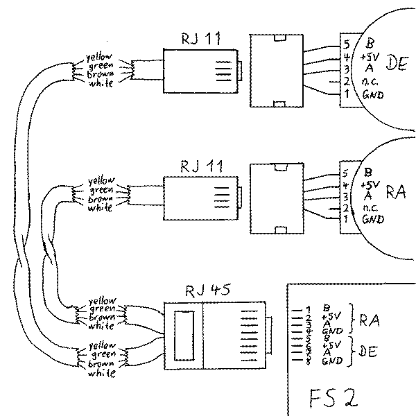
27.
Pinbelegung der RJ12 Autoguider Buchse: 27.
Pinout of the RJ12 Autoguider connector:
Ausgänge an Kameras und Autoguidern: Output Ports of Cameras and Autoguiders:
Eingänge an Montierungen und Steuerungen: Input Ports of Mounts and Drive Units:
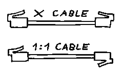
Verschiedene "RJ" Steckverbinder Some different "RJ" connectors
|
28.
Anleitung zur genauen Polachsen-Justierung nach der Scheiner-Methode
von Franz Kersche und Gerald Rhemann ( www.astrostudio.at ) |
Download PDF | 28.
How to make the exact polar alignment (Scheiner method)
written by Franz Kersche and Gerald Rhemann ( www.astrostudio.at ), sorry in german language only |
29.
Warum hat die FS2 keine USB Schnittstelle?
Bei
der USB Schnittstelle ist die maximale Kabellänge auf 5m begrenzt,
aber viele FS2 Benutzer brauchen eine grössere Kabellänge. Die
FS2 hat eine serielle RS232 Schnittstelle weil damit problemlos bis zu
15m Kabellänge möglich ist.
|
29.
Why doesn't the FS2 have a USB port?
The
USB port allows only a maximum cable length of 5 meters, but many FS2 users
want a longer cable. The FS2 has a serial RS232 port because this allows
15 meters cable length without any problems.
|
30.
Fernsteuerung der FS2 über Bluetooth
Die folgenden Informationen wurden freundlicherweise von Markus Emmerich bereitgestellt: An
meiner FS2 habe ich das serielle Kabel durch den "Pico Plug" von
Hier ist ein sehr ausführlicher Erfahrungsbericht über die drahtlose Fernsteuerung der FS2 mittels Picoplug-Adapter und HP hx4700, geschrieben von Christian Wallasch. |
30.
Remote controlling the FS2 via Bluetooth
The following informations were kindly supplied by Markus Emmerich, translation by Michael Koch: At
my FS2 I've replaced the serial cable by the "Pico Plug" from Sphinx Electronik.
Here
is a very detailed report about wireless
remote control of the FS2 with a Picoplug adapter and a HP hx4700, written
by Christian Wallasch.
|
31.
Fehlersuche an der seriellen Schnittstelle
Wenn
die serielle Verbindung zwischen PC und FS2 nicht funktioniert, dann sollte
man folgende Punkte überprüfen:
|
31.
Debugging the serial port
If
the serial transmission between FS2 and PC doesn't work, check the following
points:
|
32.
Fehlersuche an der Autoguider-Schnittstelle
Wenn
Sie überprüfen möchten ob die FS2 Autoguider-Schnittstelle
richtig funktioniert, dann können Sie folgenden Test machen:
Verbinden
Sie Pin 4 mit Pin 5: Im Display muss TRACK > erscheinen.
Wenn
dieser Test erfolgreich verlaufen ist und die Verbindung zum Autoguider
trotzdem nicht funktioniert, prüfen Sie folgende Punkte:
Pinbelegung:
|
32.
Debugging the autoguider interface
If you want the check if the FS2's autoguider interface is working, you can make this simple test: Take a short piece of wire and connect two pins at the DB15 connector. You woun't damage the FS2 even if you connect the wrong pins accidently. Connect
pin 4 with pin 5: In the display must appear TRACK >
If
this test was successful, but the interface still doesn't work, check these
points:
Pin
assignment:
|
33.
Fehlersuche an der Encoder-Schnittstelle
Der
Schaltplan rechts zeigt die Verdrahtung der Encoder:
Debugging the encoder port The
schematic diagram shows the wiring of the encoders:
|
34.
Pinbelegung an der Handbox Pinout
of the hand control box
|
35.
Tipps zur Senkung der FS2-Stromaufnahme
-- Den Parameter "M1_Str1" möglichst klein einstellen, denn bei normaler Nachführung wird normalerweise nicht das volle Drehmoment gebraucht. Der Parameter "M1_Freq1" muss so gross einstellen, dass der grössere Strom "M1_Str2" erst bei höherer Drehzahl wirksam wird. -- Beim Deklinations-Motor kann "M2_Str1" sogar auf Null gesetzt werden. Der DE Motor muss nicht unbedingt Strom kriegen wenn er stillsteht. Dann muss aber M2_Freq1 auf 0Hz stehen, damit der Motor wieder Strom bekommt sobald er sich drehen soll. -- Das Display ist ein Stromfresser wenn es sehr hell eingestellt ist. |
35. Some hints for reducing the FS2's current intake |
36.
Berechnung der maximalen Drehzahl eines Schrittmotors
Beim Schrittmotor wird die maximale Drehzahl durch die Strom-Anstiegs-Geschwindigkeit in den Wicklungen bestimmt. Die Induktivität der Wicklungen begrenzt diese Geschwindigkeit. Berechnung der maximalen Frequenz des sinusförmigen Wicklungsstroms: fmax = U / (2 pi L Imax) Dabei
ist
Man beachte dass die Vollschritt-Frequenz um den Faktor 4 grösser ist als die Frequenz des sinusförmigen Wicklungsstroms. Um
eine möglichst hohe Frequenz (und damit Drehzahl) zu erreichen, braucht
man also
Wenn
der Motor mit einer höheren Frequenz als fmax betrieben
wird, dann ist der Wicklungsstrom kleiner als der Nennstrom, und daher
sinkt auch das Drehmoment mit zunehmender Frequenz immer weiter ab.
Beispiel:
fmax = 30V / (2 pi 5mH 1.8A) = 530.5 Hz Die nach dieser Formel ermittelte Frequenz ist allerdings grösser als die tatsächlich erreichbare Frequenz. Das liegt daran, dass der sich drehende Schrittmotor eine Spannung erzeugt (Back-EMF), die sich von der Betriebsspannung subtrahiert, so dass effektiv weniger Spannung zur Verfügung steht. Für
den ESCAP P530 Motor ist die Back-EMF im Datenblatt angegeben:
Eine verbesserte Formel unter Berücksichtigung der Back_EMF wäre dann: fmax = U / (2 pi L Imax + Back_EMF) wobei
Back_EMF in V / Hz angegeben werden muss.
Für das oben genannte Beispiel ergibt sich: fmax
=
30V / (2 pi 5mH 1.8A + 0.022 V/Hz) = 381.9 Hz
Die Frequenz des sinusförmigen Wicklungs-Stroms bei siderischer Geschwindigkeit wird so berechnet: fsid = (M1_VS/U) x (M1_Getr) / 344656 Und die maximale Schwenk-Geschwindigkeit (als Faktor bezogen auf die siderische Geschwindigkeit) ist dann: SPEED
= fmax / fsid
Beispiel:
fsid = 100 * 1728 / 344656 = 0.501 Hz SPEED = 381.9 / 0.501 = 762 In
der Praxis können höhere Geschwindigkeiten erreicht werden, wenn
man nicht das volle Drehmoment benötigt.
|
36. How to calculate the maximum speed of a stepper motor |
37.
Einstellung der korrekten Getriebe-Untersetzung bei Reibrad-Antrieben
Bei einem Reibrad-Antrieb kann die Getriebe-Untersetzung fertigungsbedingten Toleranzen unterliegen. Daher muss sie für jede Montierung individuell ermittelt werden, wenn höchste Genauigkeit beim Positionieren und bei der Nachführ-Geschwindigkeit gewünscht wird. 1. Wenn Encoder vorhanden sind, dann werden sie erst einmal ausgeschaltet (Parameter "Diverses/Encoder" auf "nein" stellen). 2.
Man beginnt mit einem geschätzten Wert für die Getriebeuntersetzung.
3. Für die folgenden Versuche sollte die Montierung korrekt eingenordet sein. 4. Jetzt macht man probeweise ein paar Goto-Schwenks über grössere Distanzen, und beobachtet wie genau das Objekt getroffen wird. Die Frage ist, ob der Motor zu weit läuft, oder ob er schon vor dem Ziel anhält. Diese Frage muss für beide Achsen getrennt untersucht werden. 5.
Wenn der Motor nicht weit genug gelaufen ist, dann muss der Parameter "Mx_Getr"
vergrössert werden.
6.
Bei der RA-Achse kann man auch die Nachführ-Geschwindigkeit als Kriterium
heranziehen.
7.
Bei den Parametern "M1_Getr" und "M2_Getr" können nur ganze Zahlen
eingestellt werden. Das kann ein Problen darstellen, wenn beispielsweise
der Wert 3200 zu klein ist und 3201 schon zu gross ist. Wenn wir annehmen
dass der korrekte Wert 3200.5 ist, dann hätten wird einen prozentualen
Fehler von 100% * 0.5 / 3200 = 0.015%.
|
37.
How to set the correct gear ratio for a friction drive
The gear ratio of a friction drive may have tolerances due to manufacturing. That's why the gear ratio must be set individually for each mount, if highest positioning accuracy and tracking speed is desired. 1. If the mount has angle encoders, please switch them off preliminary (set parameter "misc/encoder" to "no"). 2.
Begin with a known value for the n
The recommended procedure for fine tuning the parameters is as follows: 1.
Switch off the encoders, set the "misc/encoder" parameter to "no".
|
38.
LX200 Kommandos für Koordinaten
Kurzes
Format:
Langes
Format:
Wichtig:
|
38.
LX200 Commands for Coordinates
Short
format:
Long
format:
Important:
|
39.
Wieviele Einträge hat die PEC Tabelle?
Bei allen Software-Versionen bis V1.21 errechnet sich die Anzahl der Tabelleneinträge nach diese Formel: PEC_Tablength = M1_Gear * M1_VS/R / 4 / Z mit
Die
so ermittelte Zahl wird sooft durch 2 geteilt, bis sie kleiner oder gleich
2000 ist.
|
40.
Ist es möglich, den RA Motor über die RS232 Schnittstelle anzuhalten?
Ja,
es gibt einen einfachen Trick, der dies ermöglicht:
Hinweis: Dieser Trick funktioniert nicht, wenn zuvor an der Handbox die Nachführ-Geschwindigkeit umgeschaltet wurde auf Mond, Sonne, Erde oder Kometen. |
40.
Is it possible to stop the RA motor over the RS232 port?
Yes,
there is a simple trick:
Note: This trick won't work, if you have changed the tracking speed at the handbox to moon, sun, earth or comet. |
41.
Kann die FS2 auf der südlichen Hemisphäre verwendet werden?
Ja,
das ist möglich. Wenn Sie von der nördlichen in die südliche
Hemisphäre reisen, müssen Sie für beide Motore die Drehrichtungen
ändern. Das sind die Parameter M1_L/R und M2_L/R.
|
41.
Can I use the FS2 in the southern hemisphere?
Yes,
that's no problem. When you travel from the northern to the southern hemisphere,
change the turning direction of both motors. That are the parameters M1_L/R
and M2_L/R.
|
42. Must the autoguider be calibrated after a meridian
flip? Answer: No, if the FS2 knows that a meridian flip was made. That means you must either have encoders connected, or after the meridian flip you must enter a new reference object and answer the E/W question correctly. This works with V1.17 and all later versions. You can make this test: Connect 4 pushbuttons to the FS2's autoguider input, and call these buttons -X, +X, -Y and +Y. Put a camera on the telescope and view the image on a screen. Call the directions on the screen "left", "right", "up" and "down". Step 1: Point the telescope to a star in the east. Give the FS2 a reference object and answer the east/west question with "E". Now press the buttons one after the other and observe in which direction the star moves on the screen: -X right +X left -Y down +Y up Step 2: Manually make a meridian flip and point the FS2 to a star in the west. The FS2 doesn't know that a meridian flip was made. Now press the buttons one after the other and observe in which direction the star moves on the screen: -X left +X right -Y down +Y up In this case autoguiding would no longer work, because the RA directions have changed. Step 3: Leave the telescope pointing to the same star as in step 2, but now give the FS2 a new reference object and answer the east/west question with "W". Now the FS2 knows that a meridian flip was made. Now press the buttons one after the other and observe in which direction the star moves on the screen: -X right +X left -Y down +Y up In this case autoguiding should work with the same calibration as in step 1, because all directions are the same. |
43.
Kann man über die serielle Schnittstelle eine Referenzposition setzen, nachdem die
FS2 eingeschaltet wurde?
Ja, das ist möglich. Allerdings ist es nicht möglich, über die serielle Schnittstelle die Ost/West Frage zu beantworten. Die FS2 geht in diesem Fall davon aus, dass die Antwort auf die Ost/West Frage die gleiche ist wie beim letzten Referenzobjekt. |
43.
Is it possible to set a reference position over the serial port, after the FS2
has just been powered on?
Yes, that's possible. However it's not possible to answer the East/West question over the serial port. In this case the FS2 assumes that the answer to the East/West question is the same as with the last reference object. |